A fertilizer plant customer was facing serious problems with liquid carryover. Munters suggested two different solutions and solved the problem according to customer expectations.
Snabbfakta
- Customer: Fertilizer plant
- Location: Southern coastal India
- Tower Name: High pressure regenerator
- Tower Diameter: 3620 mm packed bed column
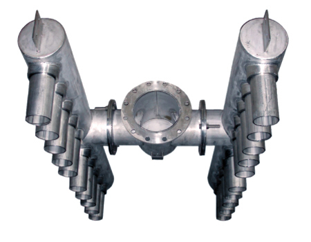
- Mass Transfer Equipment: Feed device (flash feed gallery and flash feed chamber)
Background
The customer operates one of the largest integrated ammonia-urea fertilizer plant in India, it´s a 900TPD ammonia and 1500TPD urea facility. Process overview Ammonia and urea production units generate the required hydrogen, dinitrogen 2 and carbon dioxide (CO2) feeds with a common reformer. Reformer outlet gasses are passed through the absorber, where hydrogen and other light gases are separated while carbon dioxide is removed by being absorbed in the solution. Hydrogen and other light gases along with slipped CO2 from the top of the absorber are passed to the methanation section. The methanator converts the residual CO2 to methane to increase ammonia reactor catalyst life. The rich solution from the absorber is then stripped in the regenerator and the CO2 gas used to produce urea. The lean solution from the regenerator bottom is then sent back to the absorber. Customer requirements The customer was facing serious liquid carryover problems in the stream from the regenerator top, which followed the downstream heat exchangers. Problem analysis After studying the system in order to optimize operations to increased capacity it was noted that: - The absorber was functioning normally - The regenerator column was experiencing severe liquid carryover along with the CO2 - The feed inlet nozzle was directing the inlet mixed phase feed onto the clear liquid residing on the flash feed gallery deck, which created turbulence and caused the liquid carryover problem Solutions provided After studying all the equipment in the CO2 removal section and conducting a detailed hydraulic check for increased capacity, the following was recommended: - Option 1: Increase the flash feed gallery vertical wall height, which would entail hot work - Option 2: Decrease the open area, thereby increasing the flash feed chamber deck area. Modify the inlet feed arrangement to facilitate lateral liquid release along the column peripheryl and then onto the flash feed gallery The customer chose option 2 along with modification of the inlet feed arrangement. The equipment was mechanically designed, manufactured and installed without any hot work to the column. Results achieved The carryover problem is solved. The CO2 removal section now runs at a increased load of 1350 MTPD.
Applikationer i detta kundcase
Snabbfakta
- Customer: Fertilizer plant
- Location: Southern coastal India
- Tower Name: High pressure regenerator
- Tower Diameter: 3620 mm packed bed column
- Mass Transfer Equipment: Feed device (flash feed gallery and flash feed chamber)


