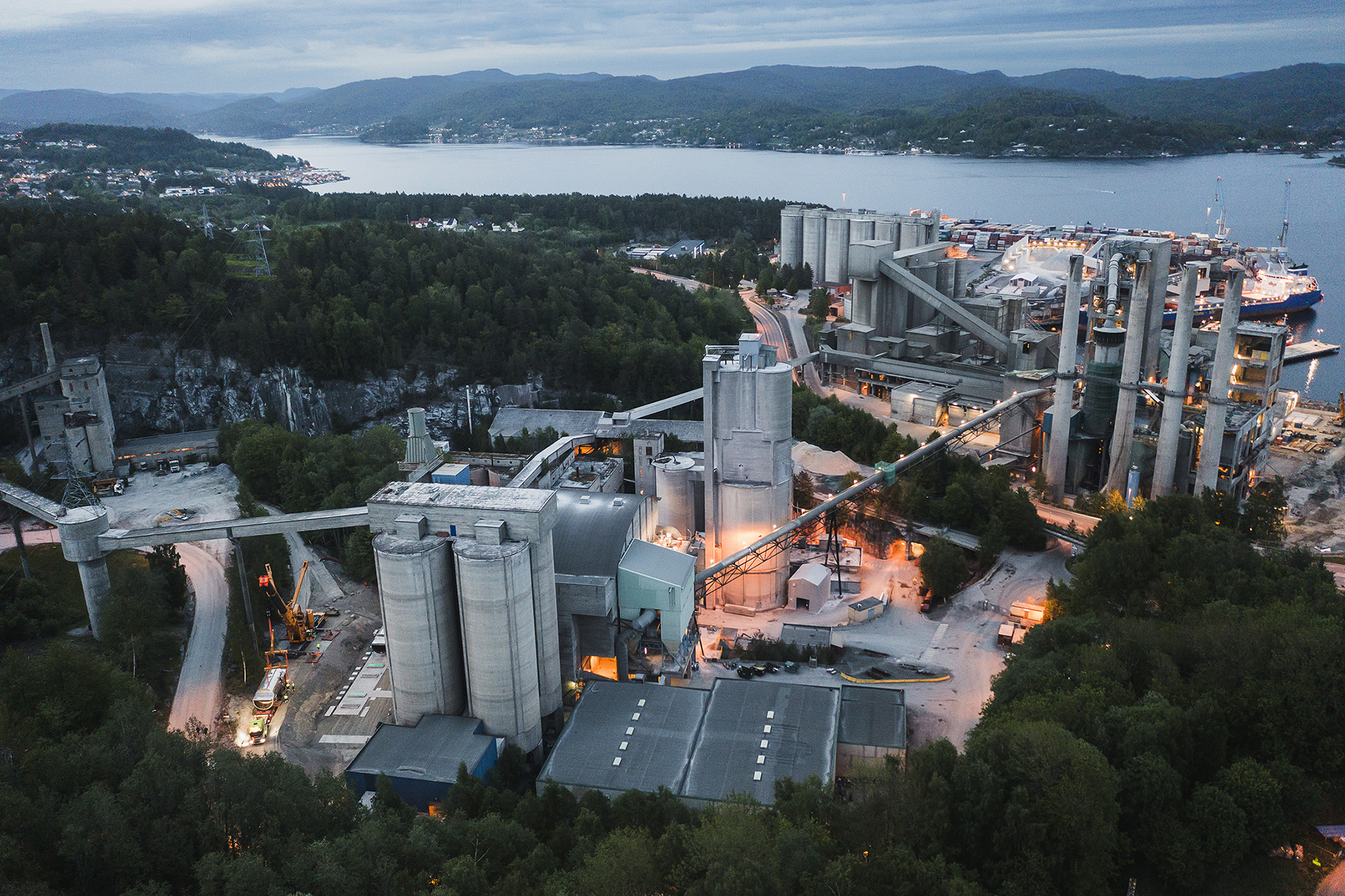
The HeidelbergCement Norcem plant is located in Brevik, in southeastern Norway and produces 1.2 milion tons of cement every year. A new, ground-breaking project is underway that will bring carbon capture to cement manufacturing for the first time ever. It is estimated that 400,000 tons of CO<sub>2</sub> will be captured per year, which gives a 50% reduction in the plant’s emissions once the carbon capture and storage operations are fully running in 2024.
Quick facts
- A yearly reduction of CO2 emissions by over 400,000 tons
- Carbon capture technology solutions will be applicable for large facilities in many industries
- Norcem Brevik carbon capture facility is scheduled to be fully operational in 2024
- MAN is supplying compression solutions that utilize Munters gas-liquid separation
Background
Cement is an essential material in almost all construction project. But cement is made from limestone, which emits high levels of CO2 when broken down. The challenge is that no green substitute for limestone exists. HeidelbergCement has found a solution that will help them meet their commmitment to being carbon-neutral by 2050. A full-scale carbon capture facility is being built at their Norcem Brevik plant. Carbon capture is the process of removing CO2 from large emission sources. The purpose of carbon capture is to limit the release of CO2 emissions into the atmosphere by capturing it and then storing it safely, for instance, in underground geological formations. The Norcem Brevik cement plant is being retrofitted with carbon capture. When fully operational, 55 less tons of CO2 will be emitted per hour, which is the equivalent of the emissions produced by 180,000 cars in a year Carbon capture process overview Flue gas is harnessed from a factory chimney, which is heated between 100°C to 165°C, and it is then cooled down to 30°C in a direct contact cooler. The temperature is reduced and caustic soda is added to remove sulfur dioxide and hydrochloric acid from the flue gas. The cold flue gas then goes to the bottom of an absorber. There CO2 molecules in the flue gas react and bind with the amine liquid inside an absorber to become a rich amine solution. The rich amine solution is then pumped into a desorber where the mixture is heated to about 120°C, which breaks the bond between the amine molecules and the CO2. The rich amine mixture is then heated and after processing in the desorber what’s left is pure CO2 gas, which goes on to be compressed and dried in the compression facility. The pressure is increased over several stages from 1.7 bar to 70 bar, and the CO2 gas is then cooled again and returns to its liquid state before the pressure is reduced to 16 bar. Liquified CO2 is then available for transit and storage.
The MAN and Munters solution
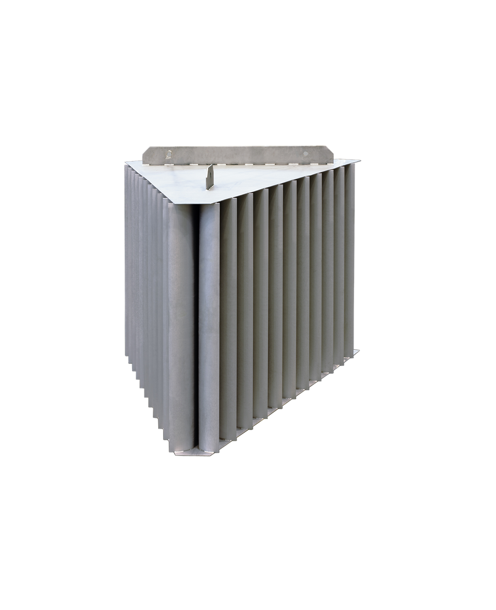
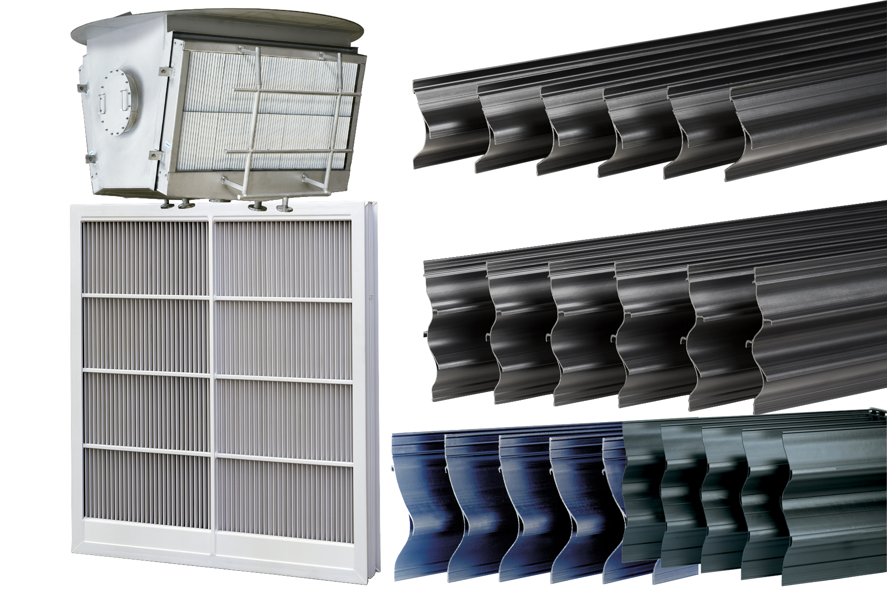
MAN Energy Solutions technologies support the extraction of pure CO2 from the plant’s emissions. MAN supplies the technology for the compression of CO2/super-critical CO2, for the liquefaction of CO2 and for heat recovery and heat integration. At Norcem Brevik, captured CO2 will be compressed before being liquefied and transported to a permanent-storage location. The transfer of heat is key for Norcem Brevik’s improved, overall power-consumption with MAN Energy Solutions able to recover heat from its compression systems that covers nearly 50% of Norcem Brevik’s power demands. MAN Energy Solutions enlisted Munters to supply critical gas-liquid separation equipment. With decades of experience with these kind of applications, skilled support staff, and satisfied customers throughout the world, Munters was the perfect partner for MAN. Munters knock out drums, or KO Drums, were chosen to be used in the compressing stages of the carbon captue process at Norcem Brevik to control condensate or liquid carryover at different stages, for example, when CO2 gas is liquified for transport. Upper separators were also supplied for use inside the vessel to enhance liquid separation and improve the performance. The KO drums feature an IDM, which is an advanced type of inlet distributor that introduces liquid mixtures into a vessel or a column. It removes liquid slugs and optimizes the downstream gas flow. The liquid removal capacity of the IDM is very high, with an efficiency of around 90%. It is designed to handle very large liquid fractions and slugs, yet it has a low pressure drop and a very high resistance to fouling. The IDM not only removes the bulk of the liquid, it also evenly distributes the onward gas flow. The IDM features angled vanes that divide the incoming gas flow, radically reducing speed, causing liquids to coalesce and drain downwards into the vessel. This reduces the entrained liquid content by up to 90% and distributes the gas flow more evenly. Separated liquids are drained off from the bottom of the vessel to eliminate the risk of re-entrainment. The IDM is also effective in handling and normalizing the flow of foaming and very viscous liquids. Clean technologies by Munters in CCS Munters gas-liquid separators help anywhere liquids and gases need to be separated. Power plants, marine, steel and further process industries all benefit from Munters industry-leading expertise. Munters gas-liquid separation enhances process productivity, lowers emissions and helps reduce the environmental footprint of our customers. Gas-liquid separation is just one of the Clean technologies by Munters. Additionally, Munters can also offer Mass Transfer technology for different unit operation processes in CCS applications, and VOC abatement removes polluting solvents from the air. Clean technologies by Munters enhance process productivity while lowering emissions and reducing carbon footprint. Technologies that deliver clean air to the world.
Applications in this case
Quick facts
- A yearly reduction of CO2 emissions by over 400,000 tons
- Carbon capture technology solutions will be applicable for large facilities in many industries
- Norcem Brevik carbon capture facility is scheduled to be fully operational in 2024
- MAN is supplying compression solutions that utilize Munters gas-liquid separation


